Watch the launch in action, and hear about the process from the project team
In Cooper Landing, Alaska, the Juneau Creek Bridge is more than a major new crossing on the Sterling Highway MP 45–60 Project. It is a construction challenge shaped by canyon access, seasonal weather, high winds, complex steel behavior, and the need to execute one of the most demanding bridge launches Traylor has undertaken.
The bridge spans Juneau Creek Canyon, a deep and environmentally sensitive crossing in Southcentral Alaska. With limited access from below and a short construction season that typically runs from mid-April through mid-October, the team had to develop an erection method that reduced work in the canyon, improved safety, and gave the project the best chance of controlling schedule and risk.
Early in planning, the team evaluated multiple ways to get the bridge in place. One option considered was a tied-arch bridge, which would likely have required a cantilever-style erection method given the depth of the canyon and limited access from below. That option carried significant temporary works and wind exposure risk, particularly because any partially completed structure could have remained exposed through seasonal shutdowns.
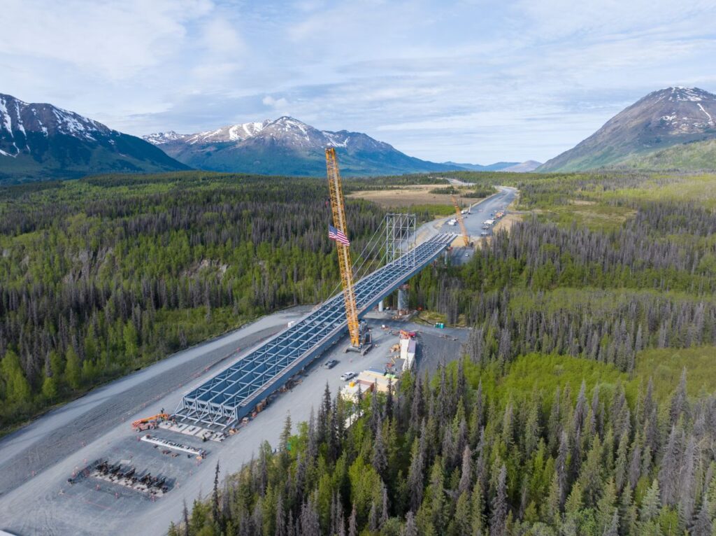
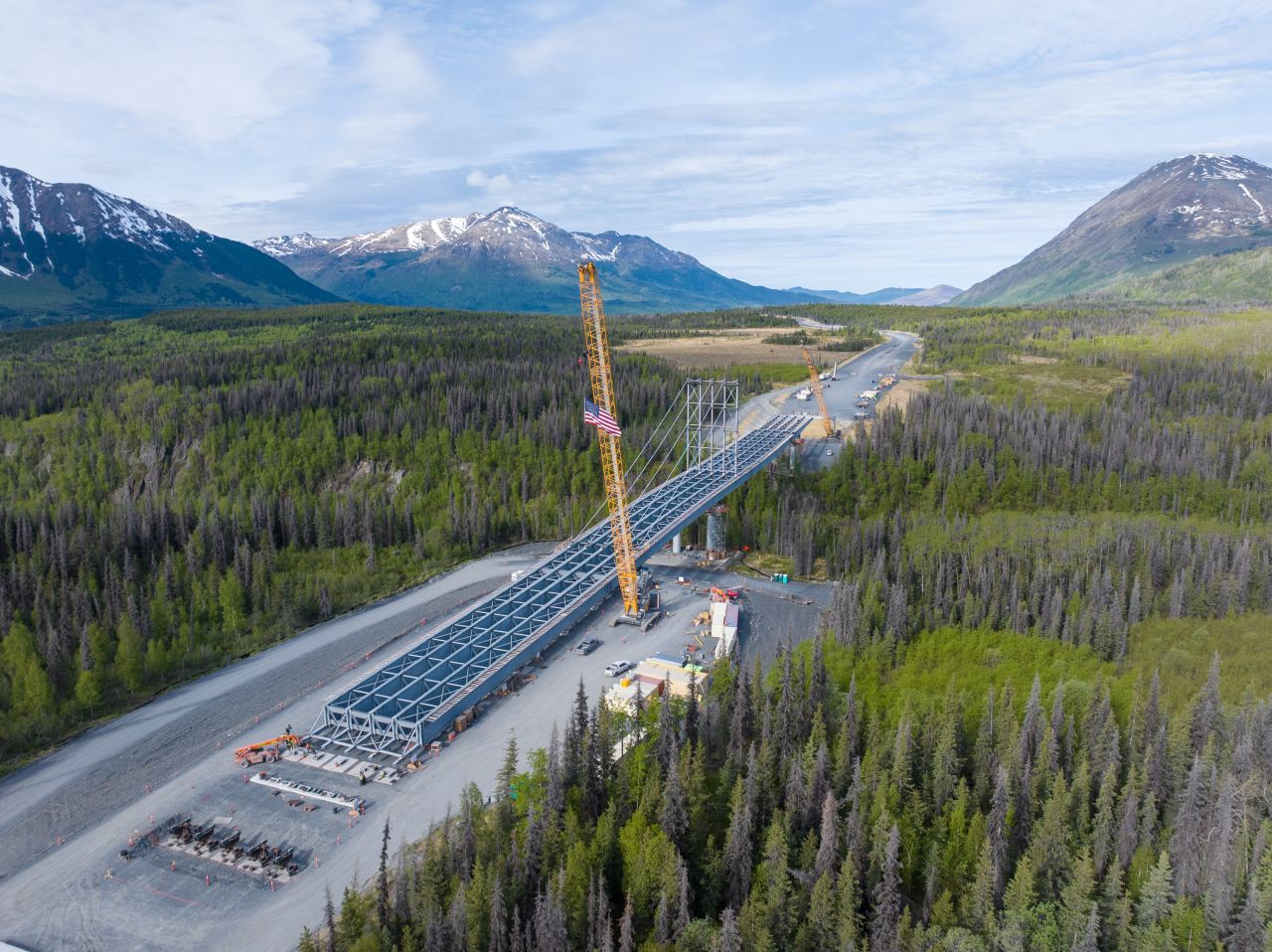
The steel plate girder solution gave the team more control. Instead of building out into the canyon over multiple seasons, the full bridge length and width could be assembled in a launching bed on the east side of the canyon. The launch could then be scheduled during the summer window, when the temporary wind criteria were significantly lower than the full year-round design wind demand. That ability to control both the work location and the timing of the highest-risk operation was a major reason the launched steel plate girder method was selected.
Not a Typical Launch
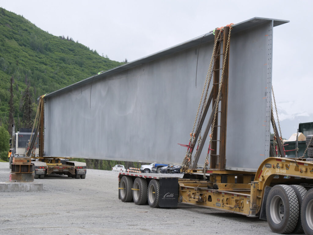
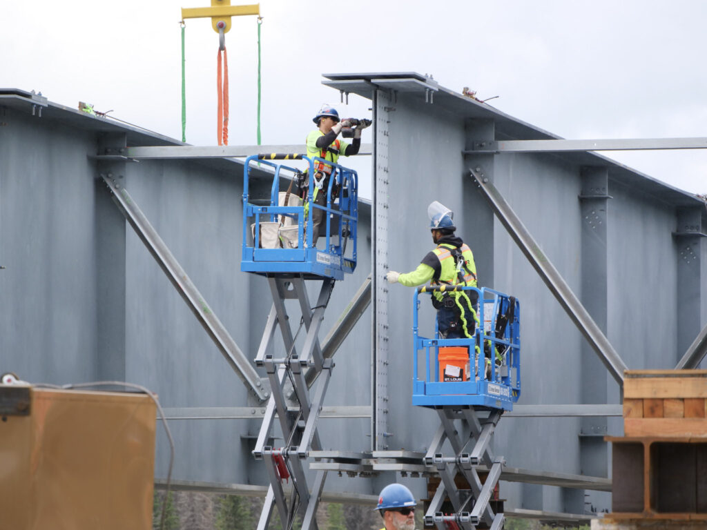
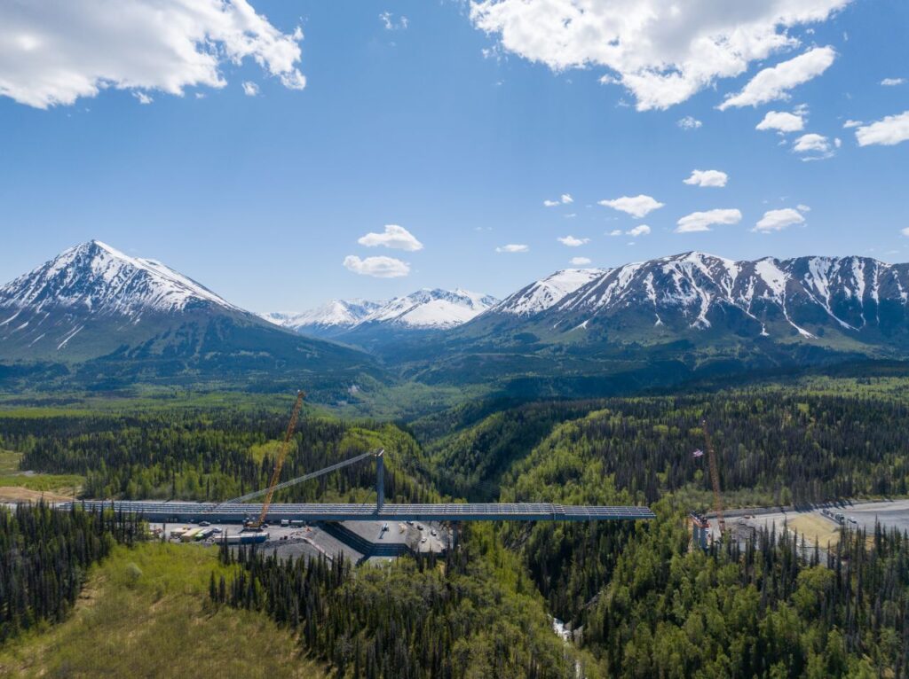
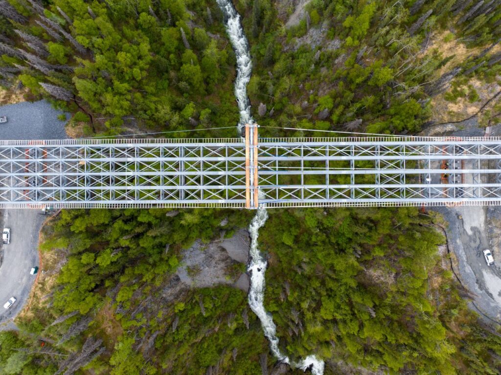
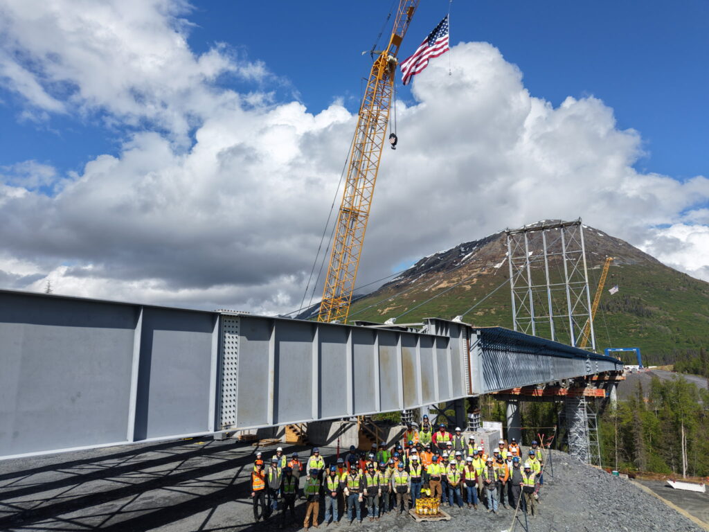
This was not a traditional incremental launch where short segments are assembled and pushed forward in repeated cycles. The full bridge length and width were assembled in the launching bed during the season prior to launch. Once the full steel superstructure was erected, the bridge was launched across the canyon as a complete five-girder-line system.
That distinction matters. Launching a five-girder steel plate girder bridge is very different from launching a two-girder system, a box girder, or a structure that can be treated more simply during temporary conditions. With five girder lines moving together, the bridge behaves as a highly indeterminate structure. Small differences in support elevation, fabrication tolerances, stiffness, friction, wind, or roller behavior can shift load from one girder line to another.
For the team, the challenge was not just to move the bridge forward. It was to control the structure at every stage of the move.
Engineering Control into the Operation
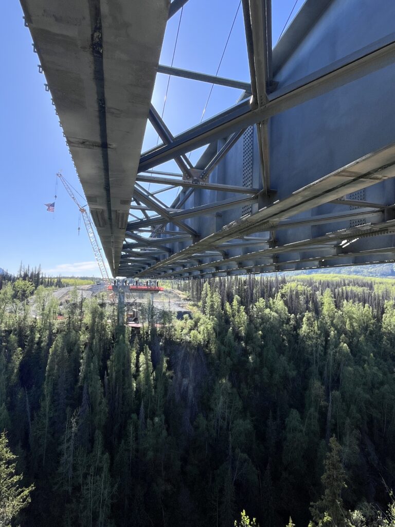
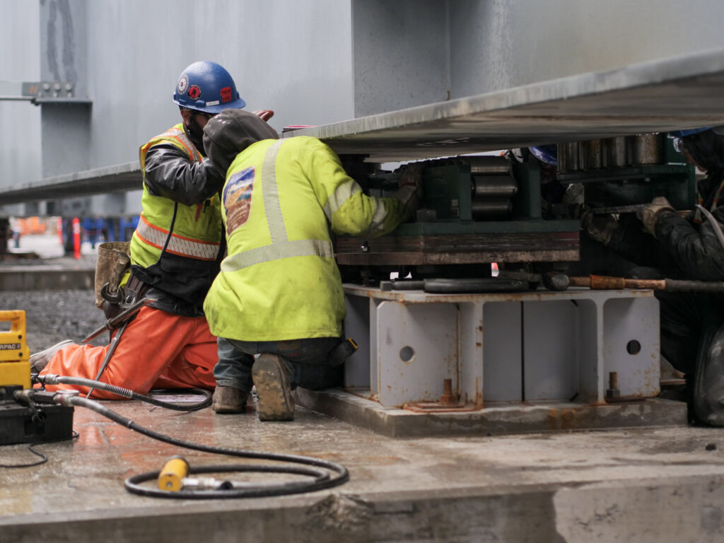
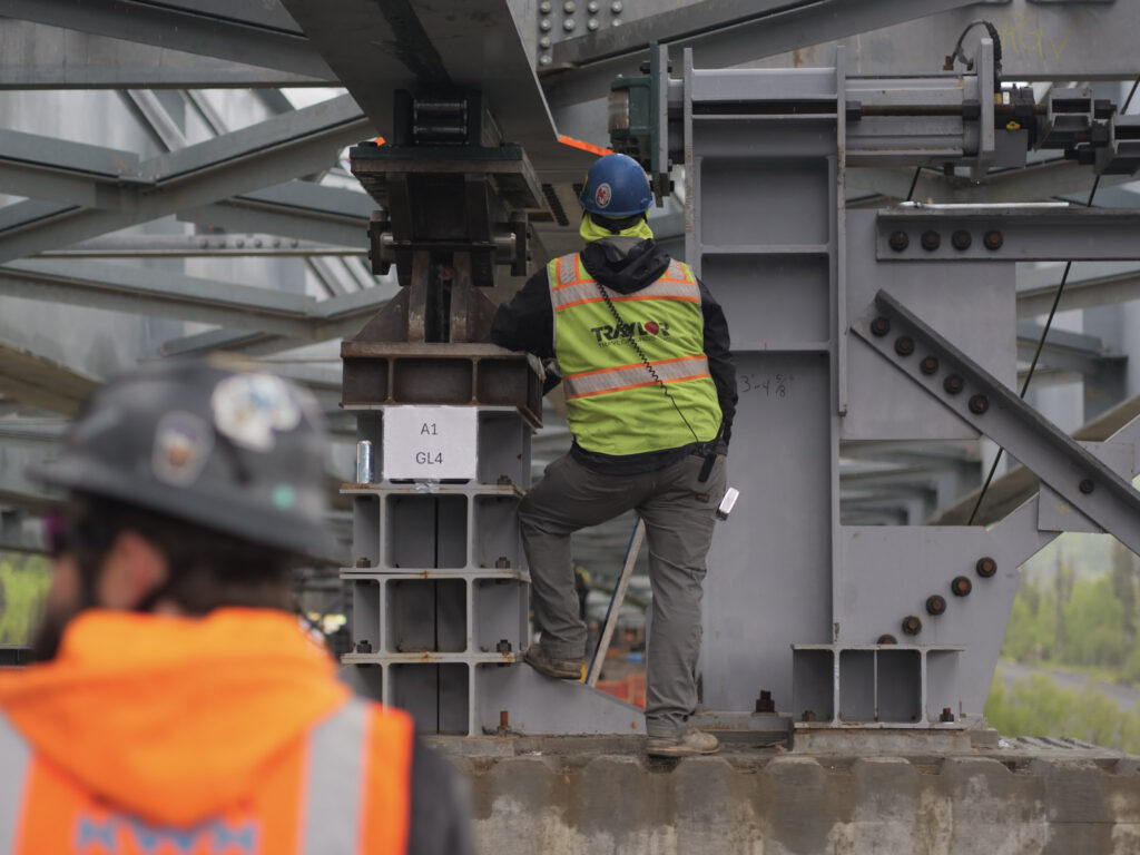
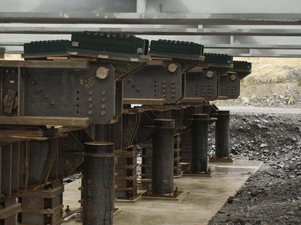
The launch was treated as an integrated structural and mechanical system. The permanent girders, cross frames, lateral bracing, launch nose, king posts, stay cables, launching tail, rollers, lateral guides, hydraulic pushing system, and load monitoring system all had to work together.
COWI, serving as erection engineer, developed the launch scheme in coordination with the project team. The launch was analyzed in detail, including 3D modeling of the five girder lines, camber, cross frames, bracing, temporary works, roller supports, lateral guides, king posts, stay system, launch nose, and launching tail. Rather than evaluating only a few broad stages, the launch was modeled at close intervals throughout the move to understand how reactions, stresses, and deflections changed as the bridge advanced.
One of the key innovations was allowing controlled movement within the system. Because the five-girder bridge could not be treated as a rigid, perfectly uniform structure during launch, the team designed ways to avoid locking in unintended forces. The goal was to give the system enough flexibility to tolerate predicted movements while maintaining the stability needed to safely launch the structure.
The team also incorporated real-time load monitoring at the piers. This allowed the field team to see the reaction at each girder line during the launch and make adjustments if differential loading approached design limits. That monitoring capability changed the nature of the operation. The launch was not based only on calculated assumptions made in advance; it became a measurable and adjustable field operation.
Launch Nose, King Post, and Deflection Control
Another major challenge was controlling deflection as the bridge advanced across the canyon. The launch nose had to strike a difficult balance: light enough to avoid adding unnecessary temporary load to the bridge and substructure, but stiff enough to carry the anticipated reactions and help control deflection as it reached the receiving supports.
To achieve that balance, the launch nose was designed as a lightweight, high-strength steel system. It extended ahead of the permanent girders and helped reduce the effects of the long cantilever condition during launch.
The king post and stay system also played a critical role. As the bridge cantilevered over the canyon, the king post helped reduce vertical deflection so the nose could reach and engage the receiving pier support system. Without that deflection control, the bridge could have approached the pier too low, requiring additional recovery measures. The king post and stay system allowed the team to keep the geometry within a manageable range during the most critical stages.
Tripping the king post in preparation for launch
Wind as a Design Driver
Wind was one of the defining features of the project. The Juneau Creek Canyon acts as a natural wind funnel, and the bridge deck sits hundreds of feet above the canyon floor. The completed bridge is designed for very high wind demands, including a 146 mph 3-second gust.
For the launch, the team worked with RWDI to develop site-specific wind criteria. Because the launch was planned for a shorter summer window, the temporary launch wind criteria were significantly lower than the full year-round wind demand. Even with that reduction, wind remained a major design driver.
RWDI also performed an aerodynamic assessment of the structure during critical launch stages. The evaluation included flutter, vortex-induced oscillation, and galloping. While the bridge was found stable for flutter and galloping, vortex-induced oscillation load cases were developed and incorporated into the launch design.
This level of wind evaluation helped the team account not only for maximum wind loads, but also for the behavior of the partially launched structure under critical aerodynamic conditions. It also supported the development of work windows and go/no-go criteria for the field.
Critical Moments During the Move
The most critical parts of the launch were the transitions. Any time the bridge changed support conditions, the team had to carefully monitor reactions, alignment, lateral movement, and system behavior.
The operation started with transferring the bridge from the assembly supports onto the launch rollers. The first major field challenge was breaking friction and initiating movement in a controlled way. From there, the bridge advanced in controlled strokes using hydraulic cylinders.
As the bridge moved forward, the team monitored girder-line reactions, lateral guide behavior, survey data, and wind conditions. The nose touchdown at each receiving support was a critical point because load began transferring through the nose, equalizers, rollers, and pier support systems. Transitions at the interior piers required particular attention because girder-line load distribution could shift rapidly.
Once the bridge reached its final position, the team still had to complete the jackdown operation, transferring the structure from the launch system onto its permanent bearing elevations. The launch was not complete until those final support conditions were safely achieved.
Lessons for the Future
The launch reinforced an important lesson: complex bridge launches are not simply about pushing steel forward. They are about controlling every support transition, every load path, and every opportunity for the structure to behave differently than expected.
The team learned valuable lessons. Those lessons will be useful not only for future launches, but for any complex operation where temporary works, structural behavior, specialty equipment, and field execution must function as one system.
A Controlled Approach to High Risk
The Juneau Creek Bridge represents innovation through disciplined risk management. The project combined a full-bridge steel plate girder launch, a five-girder indeterminate structural system, real-time load monitoring, a lightweight high-strength launch nose, king post deflection control, site-specific wind analysis, aerodynamic assessment, hydraulic control, lateral guidance, and field-driven contingency planning.
The result was not simply a bridge launch. It was a controlled, monitored, and adjustable construction operation designed for one of Alaska’s most challenging bridge sites.
For Traylor, the Juneau Creek Bridge launch is a strong example of what heavy civil construction requires at its best: technical creativity, field leadership, specialty engineering, planning discipline, and the willingness to take on difficult work while actively managing the risks that come with it.